
Preparing for 3D printing
Choosing your own printer, being warned when something does not fit, and laying the part the right way.
Choosing your printer
Open the settings (the cogwheel in the title row, “Workspace settings”) and switch to the area “Workplane”. Under “Printer” you pick your printer from a list of over 230 common models, including Bambu Lab, Prusa, Creality, Anycubic, Elegoo and many more.
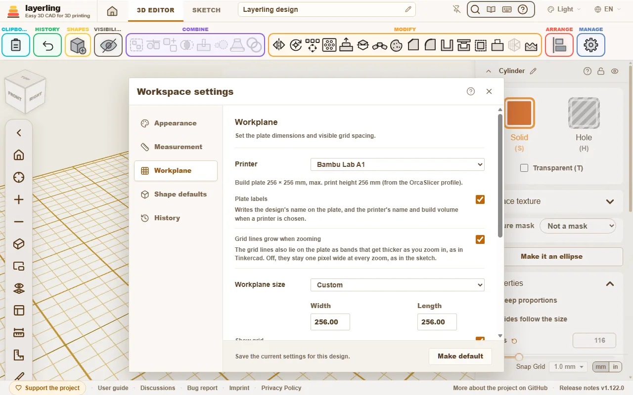
Three things happen:
- The workplane takes the size of the print bed.
- In the corner of the workplane appear the printer's name and its build volume. If the writing gets in the way, switch it off with “Plate labels” under “Workplane”; that also goes for the design's name at the front left.
- layerling warns when something does not fit.
The printer profiles come from OrcaSlicer, so they are the same ones your slicer knows. If you would rather work without a printer, choose “No printer - free size”. You can also set the size of the workplane by hand.
Delta printers such as those by FLSun or SeeMeCNC, or the Anycubic Predator, print on a round plate. With one of them the workplane is round too, as wide as the plate, and a body is too large as soon as it reaches past the rim. A round body is measured by its own outline, not by the box round it, so a cylinder nearly as wide as the plate still fits.
When something does not fit
A body that sticks out over the edge of the print plate is marked. A message tells you which sides overhang and by how much. It is the same if the part is too tall: the height counts from the lowest body, just as the slicer sets the model down.
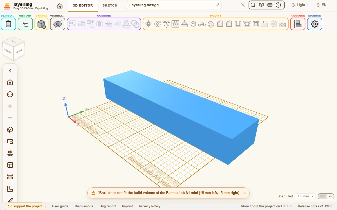
The warning does not stop you from working on. It is a hint so you do not find out only in the slicer that the part is too big. A part that is too big can often be split: cut it in two with “Split” and print both halves separately.
If you park parts beside the plate on purpose, click the small cross in the message. The warning is then gone for exactly these bodies. Once one of them fits again and you move it out later, or another body sticks out, the message comes back. Hidden bodies never count, so hiding the parked parts works as well.
Laying the part right
How a part lies on the plate decides its strength and looks. Two tools in the “Arrange” area help:
- “Lay flat on face”: click a face and the part lies with that side down. The best print direction in one click.
- “Drop to workplane” (D): sets the part on the workplane when it floats somewhere in the air.
A few rules of thumb for direction:
- Large flat faces down. They stick best.
- Lay long, loaded parts so the layers do not run perpendicular to the load. Layers are the weakest direction.
- Avoid overhangs steeper than 45°, or give them supports in the slicer.
Finding overhangs
In the menu next to the eye (“Visibility”), Show overhangs switches the overhangs on. Every face that points down more steeply than 45° is then hatched red and white - that is where the printer would need supports. What rests on the plate stays clear. So you see while designing whether a sphere, an arch or a horizontal hole prints without supports; the teardrop hole is made for exactly that. Turn the part or lay it on another face with “Lay flat on face”, and the hatching follows at once.
How steep your printer manages is set in the settings under “Appearance”: from 30° (careful) to 70° (for printers with good part cooling). A face resting on another body is still marked - layerling only looks at the face itself.
Wall thickness, clearance and chamfers
- Walls should be at least two extrusion lines wide, so 0.8 mm with a 0.4 mm nozzle. Sturdy parts need 1.2 to 2 mm.
- Where two parts fit into each other you need clearance: usually 0.2 to 0.4 mm, depending on the printer. Make a small test pair before you print the big part.
- Many people lightly chamfer the lower edge that sits on the plate. That keeps the first layer from spreading ("elephant foot").
Your printer's play: the fit test
Every printer prints holes a little smaller and pins a little thicker than they are drawn, each by its own amount, so the clearance two printed parts need is a guess at first. Measure it once instead. In the settings under “Workplane”, “Make fit test” puts a fit test on the plate: a 60 × 20 × 4 mm plate with seven holes for one 5 mm pin, each drawn 5 mm plus twice 0.05, 0.10, 0.15, 0.20, 0.25, 0.30 or 0.40 mm, the value raised beside it, and the 5 mm pin itself, standing beside the plate with a small chamfer on top. It is made of ordinary shapes, so it prints with the rest of the plate, without supports.
Print it as it lies, then push the pin, chamfered end first, into the holes from the tightest on. The snuggest hole the pin still turns in gives your printer's play. Type its number under “Printer play”, or click it among the values below the field. The play is per side, in millimetres, and the browser keeps it for every design; an empty field means not measured.
From then on, new uses start from the play instead of the built-in value: “Gap per side” and “Pin play (per side)” in the “Lid” tool, the clearance of a new “Dovetail” and “Snap-fit”, “Clearance (XY)” of a new nut or tapped hole - twice the play, as that is the room across the whole diameter - and “Minimum gap” in “Check clearance”. While such a field still holds that value, "“From your fit test”" beside it says where the number comes from. A hinge printed in place and the joints of the “Flexi joints” tool keep their 0.4 mm: printed in one piece, their gaps also have to stay open between the layers, which a pin printed apart does not measure. Room for pressing in a magnet or a Gridfinity key, and room for a bought socket or board, keep their own values too. Bodies already in a design never change, nor does a design you open.
Checking the print
“Print check”, next to “Check clearance” in “Combine”, looks at the selected objects, or at every visible object when nothing is selected, and says in one window what would go wrong when printing. Each of its five lines is green when it found nothing, and orange with what and where when it did:
- “Thin walls”: places thinner than two lines of the nozzle - 0.8 mm with a 0.4 mm nozzle. The slicer leaves such a wall out or prints it as one weak line. Choose your nozzle under “Nozzle” at the top of the window (0.2 to 0.8 with one click, any other in the field). The thin places are painted red with a light grid on the bodies, and the line names the thinnest place and how much surface is too thin. Places smaller than 1 mm² and sharp edges, such as the edge of a wedge, are left out.
- “Floating parts”: a body, or a separate part of one, that touches neither the plate nor another part (within 0.05 mm). It would be printed in the air. A part resting on a part that stands is fine.
- “Small contact with the plate”: a part on the plate whose first layer is very small for its height, such as a sphere or a cone on its tip. It can come loose while it prints. The check warns below 0.5 mm² of footprint, measured 0.1 mm above the plate, for each millimetre of height: a sphere is always below that, a cube of 10 mm has 10.
- “Overhangs”: the same figures as Show overhangs, at the angle set there.
- “Open mesh”: an imported mesh with open edges, or edges that three or more faces share. The slicer has to guess where such a mesh is inside.
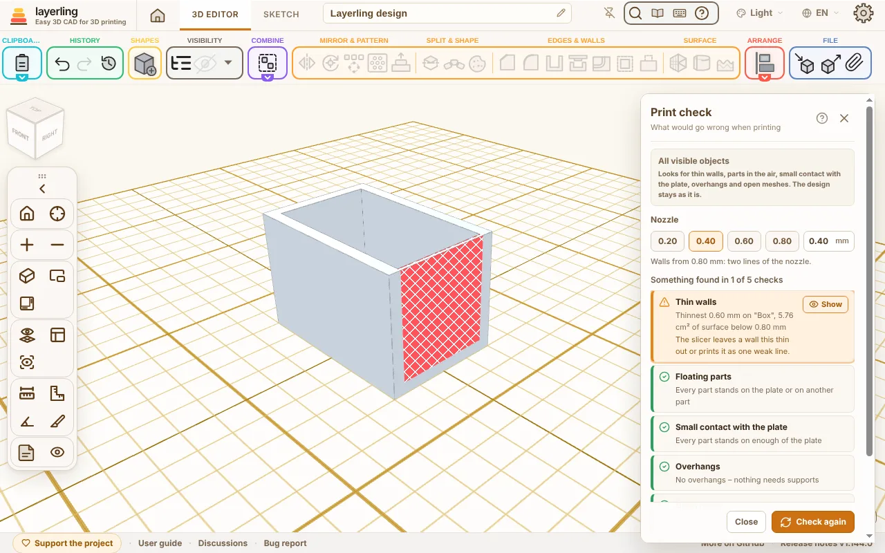
“Show” on a line takes the camera there; it selects the floating parts, those standing on too little and the open meshes, and for the overhangs it switches Show overhangs on. Bodies that overlap are checked joined, as the slicer joins them. If you change the design while the window is open, it shows “Changed – check again”; click that or “Check again”. Esc closes the window. Nothing in the design changes. An AI runs the same check with layerling_check_print.
When you are ready
Choose “Export” and then STL or 3MF. STL is the simplest format. 3MF keeps names and colours of the individual bodies and is therefore handy when you print in several colours. The export window also shows how many grams and metres of filament the part would take printed solid. More in Files and saving.